Load balancing Cisco Identity Service Engine
Updated on February 3, 2026
•
Published on December 11, 2025
Benefits of load balancing Cisco ISE
Load balancing Cisco’s Identity Service Engine (ISE) provides a number of benefits, including:
- Simplified network device configuration: Without a load balancer, every single Network Access Device (NAD)—every switch, wireless controller, and VPN gateway—must be manually configured with the IP addresses of every ISE Policy Service Node (PSN). A load balancer allows a single Virtual IP (VIP) to be configured on all network devices. If a NAD needs to be added, removed, or replaced an ISE node in the future, only the load balancer pool needs to be updated. So there’s no need to touch thousands of switches or risk outages by updating configurations on live network equipment.
- Intelligent failover and zero downtime: A load balancer actively checks the health of the ISE nodes (using advanced health monitors, not just ping) and instantly redirects traffic if a node becomes unresponsive. This allows “drain-and-maintenance” operations to be performed. It’s also possible to manually disable a node in the load balancer to let existing sessions finish, patch/reboot that ISE node, and bring it back online—all without users ever noticing a service interruption.
- Even load distribution: In a standard failover setup (Primary/Secondary), the Primary node takes 100% of the traffic until it dies, while the Secondary node sits idle. This is an inefficient use of expensive hardware. A load balancer allows for Active/Active deployment. It distributes authentication requests (RADIUS) and guest portal traffic (HTTPS) evenly across all the ISE nodes. This prevents any single node from hitting performance caps (which can cause slow Wi-Fi logins or authentication timeouts) while others sit underutilized. It ensures consistent performance for end-users, even during peak login times (e.g., 9:00 AM Monday morning).
About Cisco ISE
Cisco ISE is a network administration tool that enables the creation and enforcement of security and access policies for endpoint devices connected to the company’s routers and switches.
The purpose is to simplify identity management across diverse devices and applications.
Why Loadbalancer.org for Cisco ISE?
Loadbalancer’s intuitive Enterprise Application Delivery Controller (ADC) is designed to save time and money with a clever, not complex, WebUI.
Easily configure, deploy, manage, and maintain our Enterprise load balancer, reducing complexity and the risk of human error. For a difference you can see in just minutes.
And with WAF and GSLB included straight out-of-the-box, there’s no hidden costs, so the prices you see on our website are fully transparent.
More on what’s possible with Loadbalancer.org.
How to load balance Cisco ISE
The load balancer can be deployed in 4 fundamental ways: Layer 4 DR mode, Layer 4 NAT mode, Layer 4 SNAT mode, and Layer 7 Reverse Proxy (Layer 7 SNAT mode).
For Cisco ISE, Layer 4 NAT mode, Layer 4 SNAT mode and Layer 7 Reverse Proxy mode are used.
Virtual service (VIP) requirements
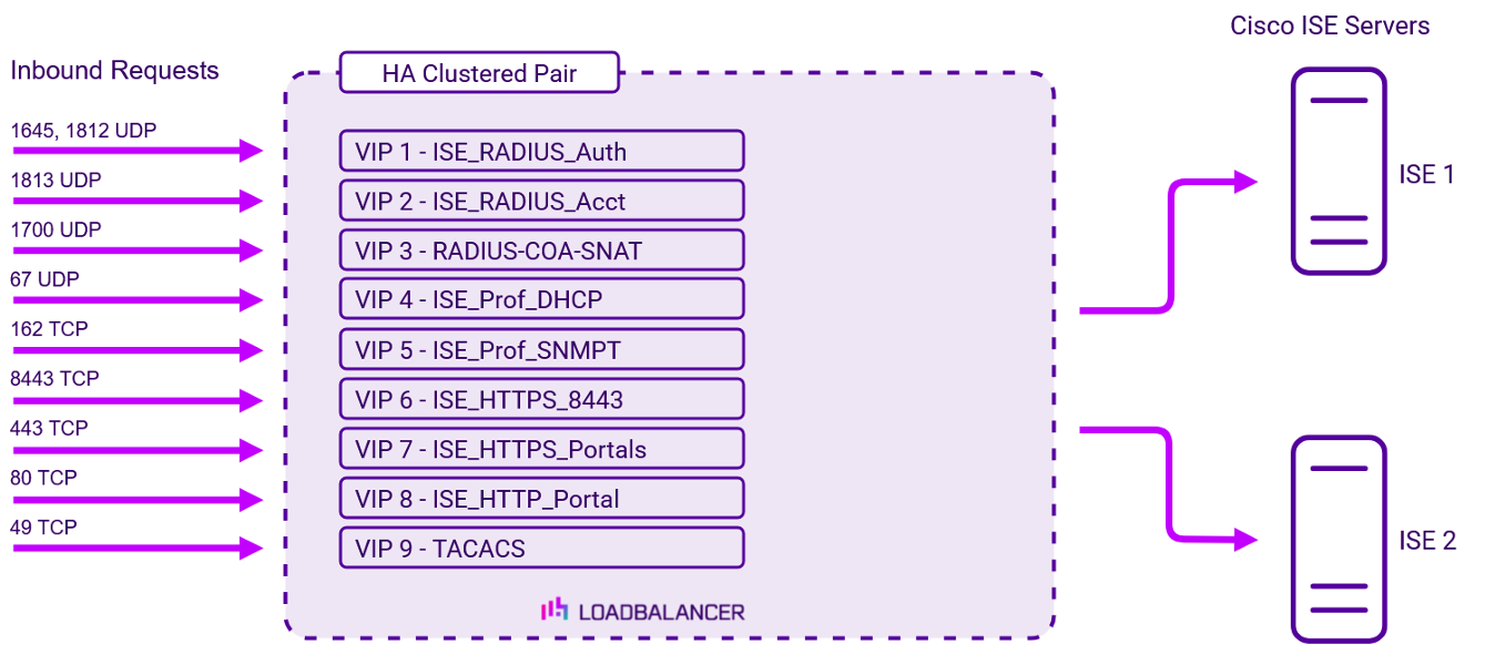
To provide load balancing and HA for Cisco ISE, the following VIPs are required:
| Ref. | VIP Name | Mode | Port(s) | Persistence Mode | Health Check |
|---|---|---|---|---|---|
| VIP 1 | ISE_RADIUS_Auth | L4 NAT (UDP) | 1645,1812 | Source IP | Negotiate RADIUS |
| VIP 2 | ISE_RADIUS_Acct | L4 NAT (UDP) | 1813 | Source IP | Negotiate RADIUS |
| VIP 3 | RADIUS-COA-SNAT | L4 SNAT (UDP) | 1700 | Source IP | Ping Server |
| VIP 4 | ISE_Prof_DHCP | L4 NAT (UDP) | 67 | Source IP | Ping Server |
| VIP 5 | ISE_Prof_SNMPT | L4 NAT (UDP) | 162 | Source IP | Ping Server |
| VIP 6 | ISE_HTTPS_8443 | L7 Reverse Proxy (TCP) | 8443 | Source IP | Negotiate HTTPS GET |
| VIP 7 | ISE_HTTPS_Portals | L7 Reverse Proxy (TCP) | 443 | Source IP | Negotiate HTTPS GET |
| VIP 8 | ISE_HTTP_Portal | L7 Reverse Proxy (HTTP) | 80 | Source IP | Negotiate HTTP GET |
| VIP 9 | TACACS | L7 Reverse Proxy (TCP) | 49 | Source IP | Connect to Port |
Load balancing deployment concept
Once the load balancer is deployed, clients connect to the Virtual Services (VIPs) rather than connecting directly to one of the Cisco ISE servers. These connections are then load balanced across the Cisco ISE servers to distribute the load according to the load balancing algorithm selected.
About Layer 4 NAT mode load balancing
This mode is a high performance solution, although not as fast as DR mode. It requires the implementation of a two-arm infrastructure with an internal and external subnet to carry out the translation (the same way a firewall works). Also, each Real Server must use the load balancer as the default gateway. Layer 4 NAT mode is transparent, i.e. the Real Servers will see the source IP address of the client.
The load balancer translates all requests from the Virtual Service to the Real Servers. NAT mode can be deployed in two-arm (using 2 interfaces), or one-arm (using 1 interface). If you want Real Servers to be accessible on their own IP address for non-load balanced services, e.g. RDP, you will need to setup individual SNAT and DNAT firewall script rules for each Real Server or add additional VIPs for this. Port translation is possible with Layer 4 NAT mode, e.g. VIP:80 → RIP:8080 is supported. NAT mode is transparent i.e. the Real Servers will see the source IP address of the client.
About Layer 4 SNAT mode load balancing
Layer 4 SNAT mode is a high performance solution, although not as fast as Layer 4 NAT mode or Layer 4 DR mode:

The load balancer translates all requests from the external Virtual Service to the internal Real Servers in the same way as NAT mode.
Layer 4 SNAT mode is not transparent, an iptables SNAT rule translates the source IP address to be the load balancer rather than the original client IP address. Layer 4 SNAT mode can be deployed using either a one-arm or two-arm configuration. For two-arm deployments, eth0 is normally used for the internal network and eth1 is used for the external network although this is not mandatory.
If the Real Servers require Internet access, Autonat should be enabled using the WebUI option: Cluster Configuration > Layer 4 – Advanced Configuration, the external interface should be selected.
Layer 4 SNAT requires no mode-specific configuration changes to the load balanced Real Servers. Port translation is possible with Layer 4 SNAT mode, e.g. VIP:80 → RIP:8080 is supported. You should not use the same RIP:PORT combination for Layer 4 SNAT mode VIPs and Layer 7 Reverse Proxy mode VIPs because the required firewall rules conflict.
About Layer 7 Reverse Proxy load balancing
Layer 7 Reverse Proxy uses a proxy (HAProxy) at the application layer. Inbound requests are terminated on the load balancer and HAProxy generates a new corresponding request to the chosen Real Server. As a result, Layer 7 is typically not as fast as the Layer 4 methods. Layer 7 is typically chosen when either enhanced options such as SSL termination, cookie based persistence, URL rewriting, header insertion/deletion etc. are required, or when the network topology prohibits the use of the Layer 4 methods.
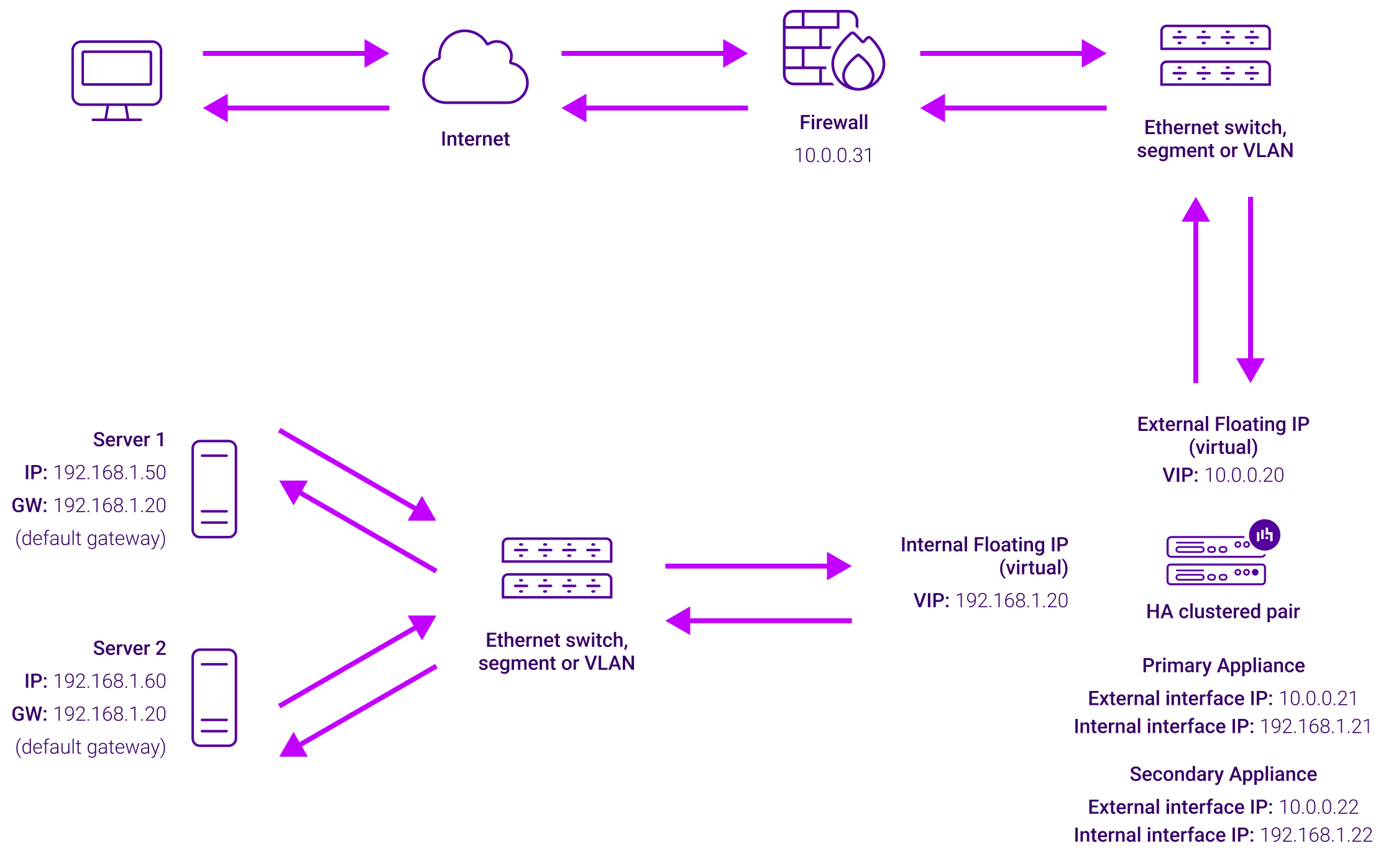
The image below shows an example Layer 7 Reverse Proxy network diagram:
Because Layer 7 Reverse Proxy is a full proxy, Real Servers in the cluster can be on any accessible network including across the Internet or WAN.
Layer 7 Reverse Proxy is not transparent by default, i.e. the Real Servers will not see the source IP address of the client, they will see the load balancer’s own IP address by default, or any other local appliance IP address if preferred (e.g. the VIP address).
This can be configured per Layer 7 VIP. If required, the load balancer can be configured to provide the actual client IP address to the Real Servers in 2 ways. Either by inserting a header that contains the client’s source IP address, or by modifying the Source Address field of the IP packets and replacing the IP address of the load balancer with the IP address of the client. For more information on these methods, please refer to Transparency at Layer 7 in the Enterprise Admin Manual.