Benefits of load balancing Pathomation PMA.core & PMA.view
Load balancing PMA.core (the back-end tile server and image management engine) and PMA.view (the front-end viewing interface) transforms a digital pathology setup from a standalone installation into an enterprise-grade ecosystem. Because PMA.core does the heavy lifting (decoding massive gigapixel slides into streamable tiles), it is the primary beneficiary of load balancing:
- High Availability (HA): In clinical and high-throughput research environments, downtime is unacceptable. If there’s a single instance of PMA.core and it crashes or requires OS patching, the entire viewing capability goes offline. However, with a load balancer sitting in front of a cluster of PMA.core servers, if one server becomes unresponsive or is taken down for maintenance, the load balancer detects this change and automatically reroutes traffic to the remaining active nodes. This means pathologists and researchers using PMA.view will not notice any service interruption. They can continue to open slides, pan, and zoom seamlessly, ensuring diagnostic workflows remain uninterrupted 24/7.
- Enhanced rendering performance: Digital pathology generates “bursty” traffic. When a user opens a slide and rapidly zooms in to 40x, or when 50 students simultaneously access a slide collection during a histology class, the server is hit with thousands of simultaneous requests for image tiles. A single PMA.core server has a finite amount of CPU and RAM to process these tile requests. A load balancer distributes these incoming HTTP requests across multiple PMA.core nodes (e.g., Round Robin or Least Connection methods). This prevents the “hourglass” effect. Users experience smooth, fluid panning and zooming in PMA.view because the computational effort of rendering the slide is shared across a farm of servers rather than choking a single machine.
- Horizontal scalability: As a laboratory grows, the volume of slides and the number of concurrent users will increase. A single server setup has a “vertical ceiling”—only add so much RAM or CPU can be added to one machine before it maxes out. Load balancing enables horizontal scaling. When the user base grows, there’s no need to rebuild the supporting architecture. Instead, simply spin up an additional standard server with PMA.core installed and add it to the load balancer pool. This allows the infrastructure to be easily and cost-effectively scaled.
About Pathomation
Pathomation is a vendor-agnostic software platform that acts as “middleware” or a “pixel broker,” allowing different types of whole slide images from various scanners to be managed, viewed, and shared across different systems. Thus overcoming some of the significant infrastructure challenges facing digital pathology.
PMA.core and PMA.view are components of the Pathomation platform. The platform is used for managing, distributing, viewing and annotating digital images of human tissue slides, scanned using any commercially available slide scanner capable of producing whole slide images in a supported file format.
Why Loadbalancer.org for Pathomation?
Loadbalancer’s intuitive Enterprise Application Delivery Controller (ADC) is designed to save time and money with a clever, not complex, WebUI.
Easily configure, deploy, manage, and maintain our Enterprise load balancer, reducing complexity and the risk of human error. For a difference you can see in just minutes.
And with WAF and GSLB included straight out-of-the-box, there’s no hidden costs, so the prices you see on our website are fully transparent.
More on what’s possible with Loadbalancer.org.
How to load balance Pathomation PMA.core and PMA.view
The load balancer can be deployed in 4 fundamental ways: Layer 4 DR mode, Layer 4 NAT mode, Layer 4 SNAT mode, and Layer 7 Reverse Proxy (Layer 7 SNAT mode).
For Pathomation PMA.core and PMA.view, Layer 7 Reverse Proxy is recommended.
Virtual service (VIP) requirements
To provide load balancing and HA for Pathomation, the following VIPs are required:
| Ref. | VIP Name | Mode | Port(s) | Persistence Mode | Health Check |
|---|---|---|---|---|---|
| VIP 1 | PMA.core | Layer 7 Reverse Proxy | 80, 443 | Source IP | Negotiate HTTP (GET) |
| VIP 2 | PMA.view | Layer 7 Reverse Proxy | 80, 443 | Source IP | Negotiate HTTP (GET) |
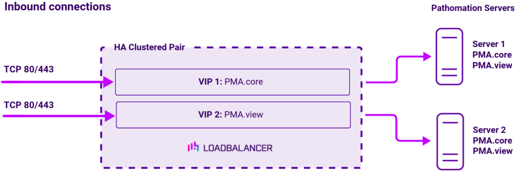
Load balancing deployment concept
Once the load balancer is deployed, clients connect to the Virtual Service (VIP) rather than connecting directly to one of the Pathomation PMA.core and PMA.view servers. These connections are then load balanced across the PMA.core and PMA.view servers to distribute the load according to the load balancing algorithm selected.
About Layer 7 Reverse Proxy
Layer 7 Reverse Proxy uses a proxy (HAProxy) at the application layer. Inbound requests are terminated on the load balancer and HAProxy generates a new corresponding request to the chosen Real Server. As a result, Layer 7 is typically not as fast as the Layer 4 methods. Layer 7 is typically chosen when either enhanced options such as SSL termination, cookie based persistence, URL rewriting, header insertion/deletion etc. are required, or when the network topology prohibits the use of the Layer 4 methods.
The image below shows an example Layer 7 Reverse Proxy network diagram:

Because Layer 7 Reverse Proxy is a full proxy, Real Servers in the cluster can be on any accessible network including across the Internet or WAN.
Layer 7 Reverse Proxy is not transparent by default, i.e. the Real Servers will not see the source IP address of the client, they will see the load balancer’s own IP address by default, or any other local appliance IP address if preferred (e.g. the VIP address).
This can be configured per Layer 7 VIP. If required, the load balancer can be configured to provide the actual client IP address to the Real Servers in 2 ways. Either by inserting a header that contains the client’s source IP address, or by modifying the Source Address field of the IP packets and replacing the IP address of the load balancer with the IP address of the client. For more information on these methods, please refer to Transparency at Layer 7 in the Enterprise Admin Manual.