
Load balancing Philips Healthcare RIS / WIM
Updated on November 25, 2025
•
Published on August 15, 2023
Benefits of load balancing Philips RIS / WIM
The three main benefits of load balancing a Philips Radiology Information System (RIS) or Workflow Information Management (WIM) platform are greater resilience, performance, and capacity management:
- High Availability (HA): Load balancing ensures continuous operation and minimizes downtime. It constantly monitors the health of all application servers. If one server fails, the load balancer automatically redirects all incoming traffic to the remaining healthy servers, preventing service disruption and ensuring radiologists and clinicians always have access to critical patient data and images (studies). It allows for essential maintenance, upgrades, or patches to be performed on individual servers without taking the entire system offline, as traffic can be temporarily rerouted away from the server undergoing work.
- Optimized performance: By intelligently distributing network requests (like image viewing or reporting requests) across multiple servers, the load balancer prevents any single server from becoming overwhelmed. It avoids service delays and system slowdowns, especially during peak usage periods (e.g., high-volume hours in the Emergency Department). This distribution ensures each request is handled by the server with the least load, leading to quicker response times for users and faster processing of imaging studies, which is crucial for timely diagnosis and patient care.
- Scalability: Load balancing allows the RIS/WIM platform to handle increasing workloads and future growth without major overhauls. As the volume of imaging studies or the number of users grows, new servers can be easily added to the existing pool. The load balancer instantly includes the new resources in the distribution logic, allowing the system to scale its capacity seamlessly. It ensures that all available computing resources are utilized efficiently, balancing the workload to maximize throughput and making the system capable of adapting to changing demands over time.
About Philips Healthcare RIS / WIM
Philips Radiology Information System (RIS) / Workflow Information Management (WIM) is a precision platform that enables enterprise-wide reading, distribution and archiving of medical images and associated data.
This single, multi-functional workspace allows radiologists to enhance the quality of their reporting, enable more effective collaboration, and improve patient care.
How to load balance Philips Healthcare RIS / WIM
The load balancer can be deployed in four fundamental ways: Layer 4 DR mode, Layer 4 NAT mode, Layer 4 SNAT mode, and Layer 7 Reverse Proxy (Layer 7 SNAT mode).
For RIS / WIM, both Layer 4 DR mode and Layer 7 Reverse Proxy mode are used.
Virtual service (VIP) requirements
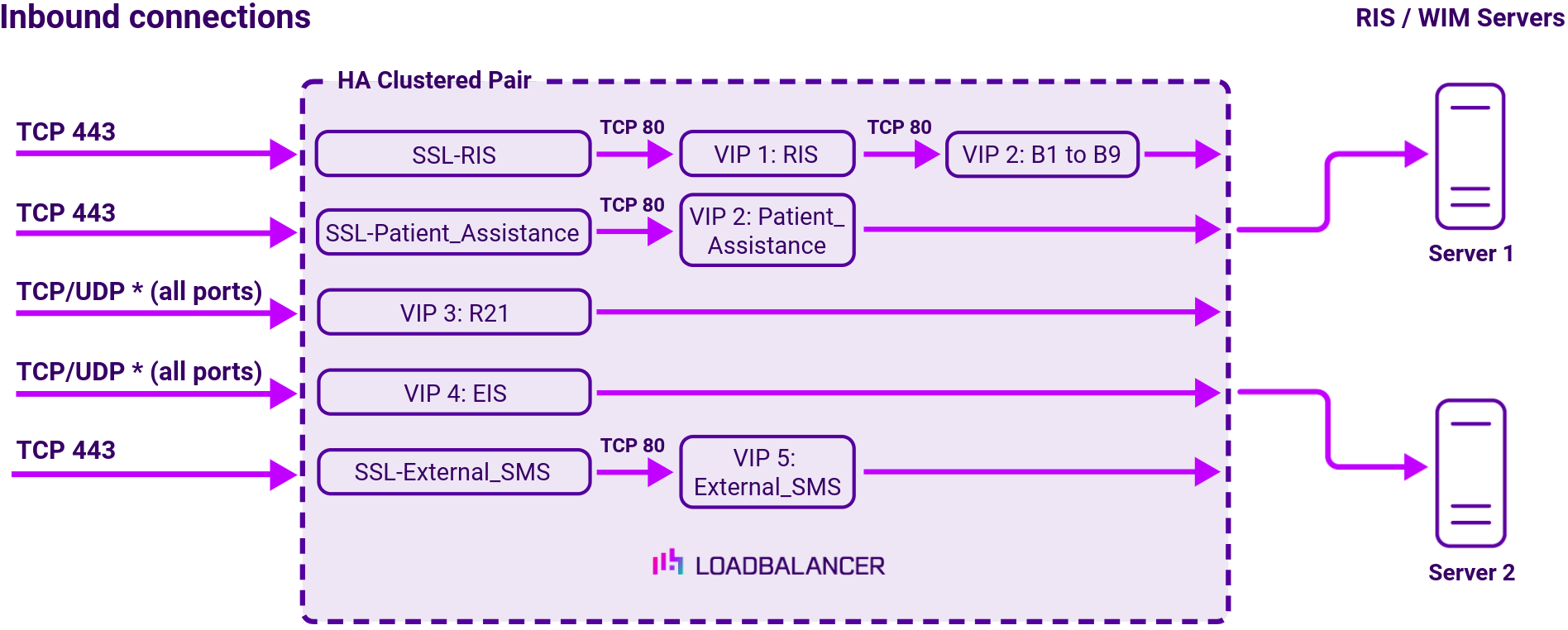
To provide load balancing and HA for RIS/WIM, the following VIPs are required:
| Ref. | VIP Name | Mode/Type | Port(s) | Persistence | Health Check |
|---|---|---|---|---|---|
| VIP 1 | RIS | Layer 7 Reverse Proxy | 80 | None | No Checks, Always on |
| VIP 1 – B1 | RIS_EM | Backend only | – | HTTP cookie | HTTPS (GET) |
| VIP 1 – B2 | RIS_IM | Backend only | – | HTTP cookie | HTTPS (GET) |
| VIP 1 – B3 | RIS_ServicesWS | Backend only | – | HTTP cookie | HTTPS (GET) |
| VIP 1 – B4 | RIS_Auth | Backend only | – | None | HTTPS (GET) |
| VIP 1 – B5 | RIS_WS | Backend only | – | None | HTTPS (GET) |
| VIP 1 – B6 | RIS_WEB | Backend only | – | None | HTTPS (GET) |
| VIP 1 – B7 | RIS_IWEB_sms | Backend only | – | HTTP cookie | HTTPS (GET) |
| VIP 1 – B8 | RIS_IWEB_gbad | Backend only | – | HTTP cookie | HTTPS (GET) |
| VIP 1 – B9 | RIS_IWEBP_ws | Backend only | – | HTTP cookie | ICMP Ping |
| VIP 2 | Patient_Assistance | Layer 7 Reverse Proxy | 80 | None | HTTPS (GET) |
| VIP 3 | R2I | Layer 4 DR | *(all ports) | None | External script |
| VIP 4 | EIS | Layer 4 DR | *(all ports) | Source IP | HTTPS (GET) |
| VIP 5 | External_SMS | Layer 7 Reverse Proxy | 80 | HTTP cookie | Connect to Port |
Load balancing deployment concept
About Layer 4 DR mode load balancing
One-arm direct routing (DR) mode is a very high performance solution that requires little change to your existing infrastructure.
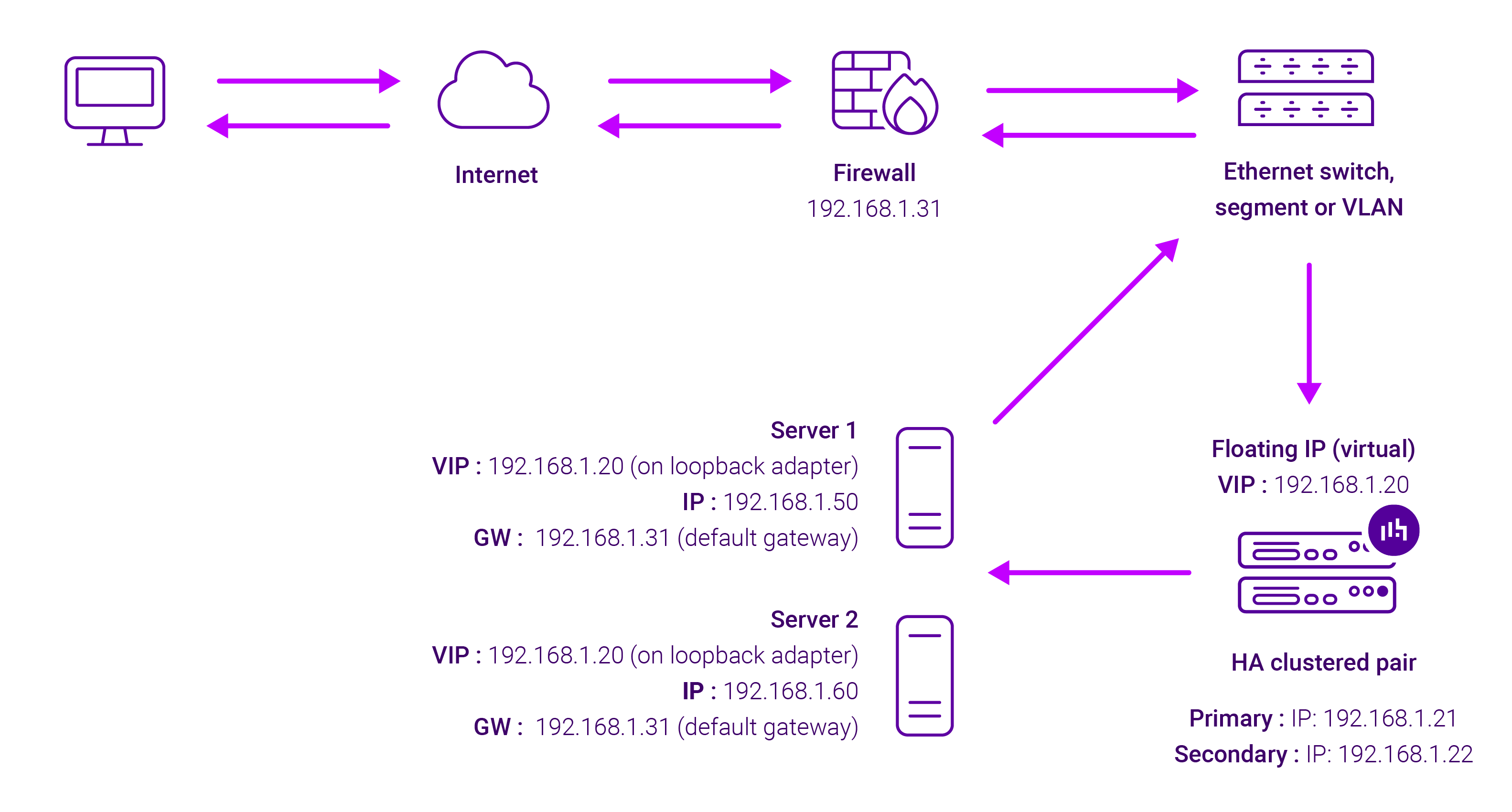
DR mode works by changing the destination MAC address of the incoming packet to match the selected Real Server on the fly which is very fast.
When the packet reaches the Real Server it expects the Real Server to own the Virtual Services IP address (VIP). This means that you need to ensure that the Real Server (and the load balanced application) respond to both the Real Server’s own IP address and the VIP.
The Real Servers should not respond to ARP requests for the VIP. Only the load balancer should do this. Configuring the Real Servers in this way is referred to as Solving the ARP problem.
On average, DR mode is 8 times quicker than NAT for HTTP, 50 times quicker for Terminal Services and much, much faster for streaming media or FTP.
The load balancer must have an Interface in the same subnet as the Real Servers to ensure Layer 2 connectivity required for DR mode to work.
The VIP can be brought up on the same subnet as the Real Servers, or on a different subnet provided that the load balancer has an interface in that subnet.
Port translation is not possible with DR mode, e.g. VIP:80 → RIP:8080 is not supported. DR mode is transparent, i.e. the Real Server will see the source IP address of the client.
About Layer 7 Reverse Proxy load balancing
Layer 7 Reverse Proxy uses a proxy (HAProxy) at the application layer. Inbound requests are terminated on the load balancer and HAProxy generates a new corresponding request to the chosen Real Server. As a result, Layer 7 is typically not as fast as the Layer 4 methods. Layer 7 is typically chosen when either enhanced options such as SSL termination, cookie based persistence, URL rewriting, header insertion/deletion etc. are required, or when the network topology prohibits the use of the Layer 4 methods.
The image below shows an example Layer 7 Reverse Proxy network diagram:

Because Layer 7 Reverse Proxy is a full proxy, Real Servers in the cluster can be on any accessible network including across the Internet or WAN.
Layer 7 Reverse Proxy is not transparent by default, i.e. the Real Servers will not see the source IP address of the client, they will see the load balancer’s own IP address by default, or any other local appliance IP address if preferred (e.g. the VIP address).
This can be configured per Layer 7 VIP. If required, the load balancer can be configured to provide the actual client IP address to the Real Servers in 2 ways. Either by inserting a header that contains the client’s source IP address, or by modifying the Source Address field of the IP packets and replacing the IP address of the load balancer with the IP address of the client. For more information on these methods, please refer to Transparency at Layer 7 in the Enterprise Admin Manual.